Machine Vision 2D / 3D Software
for measurement and image processing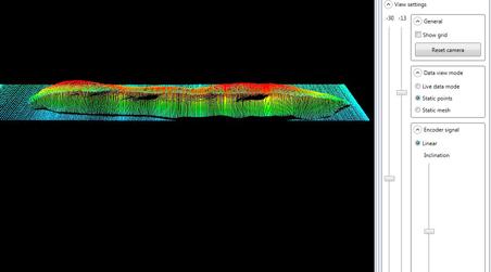
Description
The QS View software package is intended for dimensional control in 2D or 3D QS-View 2D / 3D software for all measuring tasks 3D representation of an irregular body for determination of volume and weight. With the 2D / 3D software a wide variety of parameters can be processed and displayed, e.g. length, width, angle height, gap, presence, volume (resp. weight), seam geometry (height, width), gap dimensions. Due to the modular structure of the software, customized specialties can be added any time. Each module delivers the results to an individual output module. The universal SPC interface allows simple connection to S7 controllers via Ethernet. 2D / 3D software developer kits are available for integrators with corresponding knowhow.
- Bending machine tools
- 3D measurements with contact free sensor
- Machine vision system
- 3D laser scanners
Similar products from QUELLTECH GMBH
QUELLTECH GMBH
Germany

Many materials cannot be measured tactilely, therefore non-contact thickness measurements become necessary. Especially e.g. with glowing materials, or wet processes, a continuous tactile measurement is nearly impossible. Furthermore, web speeds in plant engineering and production have increased, requiring a corresponding fast sampling rate of the measuring systems. In addition, high measuring widths are often required. Why is contact free measurement technology so perfect for this application? Can be used in any web width, Scalable measurement thicknesses from a few millimetres to several meters, Thickness and coating thickness can be measured for different materials, Vibrations of the web materials, can be compensated, Turnkey solution for mechanical engineering, Non-contact and non-destructive measurement method, Large distances to the measured object are possible, Measurement of free forms,

QUELLTECH GMBH
Germany
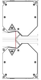
Particular Challenge: For the assessment of rotating parts, numerous parameters have to be taken into consideration: Concentricity, radial run-out and axial run-out (i.e. wobble); furthermore thickness, diameter, planarity and the absence of surface defects had to be examined. The solution developed by QuellTech consists in a configuration of three Q6 Laser Laser Scanners.Each of the lateral surfaces is assigned to its own scanner. In order to enable the thickness precisely to be determined, both laser lines are mutually oriented in opposite direction. The third scanner inspects the outer circumference of the wheel, this way measuring diameter and radial run-out. All of these scanners are subject to encoder signals supplied by the rotary axis and synchronously triggered, so possible defects on the wheel can precisely be localized. The measurement takes place at a resolution of ca. 30 µm, and a cloud comprising several millions of points are obtained.
QUELLTECH GMBH
Germany
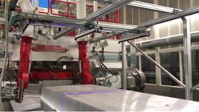
Particular Challenges of the Application: By tactile equipment, determination of the deepest point on a rough metal surface is neither simple or precise. As a consequence, often either too much material is removed, or the surface is still covered with defects which have to be eliminated by a following milling cycle. The equipment is arranged in parallel, so that the complete width of the slabs is covered. The sensors are calibrated to a common coordinate system and mounted on a movable gantry. Before measurement, the slabs are fixed in place. The scanners mounted on the gantry are guided over the measuring object, driven by an electric motor. The point cloud recorded by the four scanners is consolidated in a PC by means of the QuellTech image processing software which calculates the difference between highest and lowest point of the corresponding surface and compensates for possible inclination of the slab (detrending).
QUELLTECH GMBH
Germany
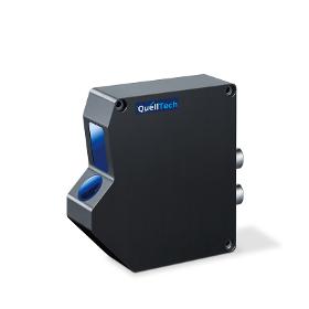
The new QuellTech Q5 Laser Scanner Series combines the advantages of small form factors with both high resolution and scan rate. The sensor disposes of different set-up possibilities with respect to the analysis algorithm. Measurement results are delivered via Ethernet, calibrated in the X / Z plane. Special adjustable algorithms can be selected, extremely useful particularly also for optically most demanding surfaces. Time-consuming calibration tasks for the user are no more required, as the calibration routine runs on board. High Scan Rate with up to 14,000 Profiles per Second Due to an appropriate limitation of the image range (AOI) in X and Z direction, the scan rate could considerably be increased. High resolution and detection frequency with up to 14.000 profiles and 28 Mio. points per second •X measuring range from 10 to 1022 mm •Z measuring range (height) from 5 to 878 mm •Laser wave length blue 405/450nm, red 650nm